180 Degrees
There's almost nothing more exciting than a package from JLCPCB awaiting by your doorstep.
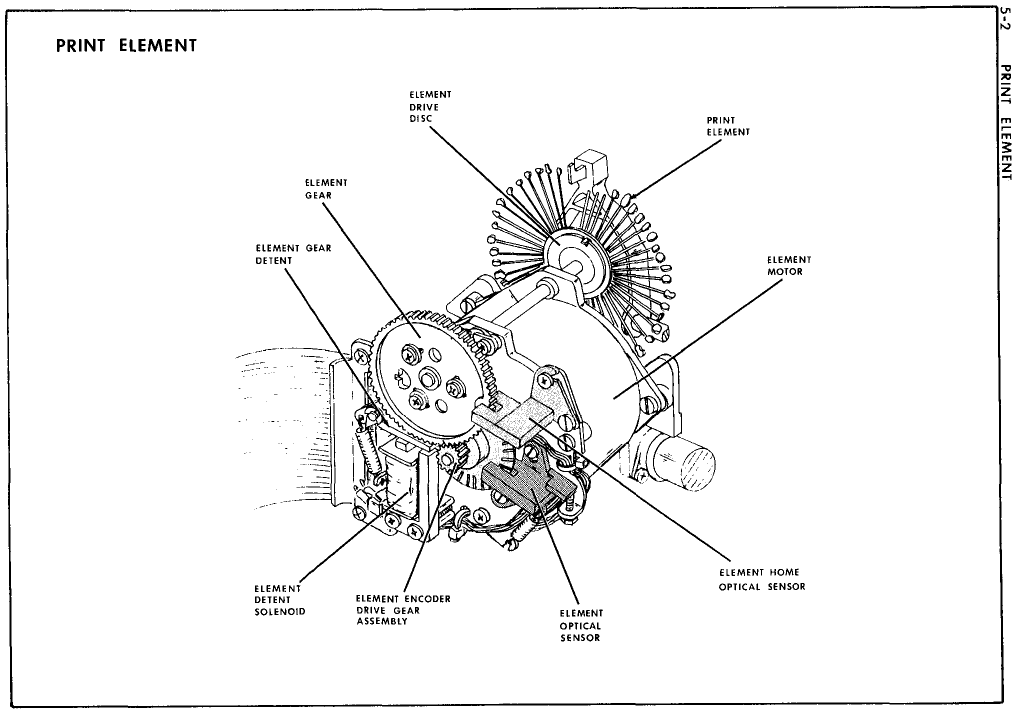
Bare board. Green. Crisp silkscreen with diagrams I picked from the Smith-Corona Service Manual.
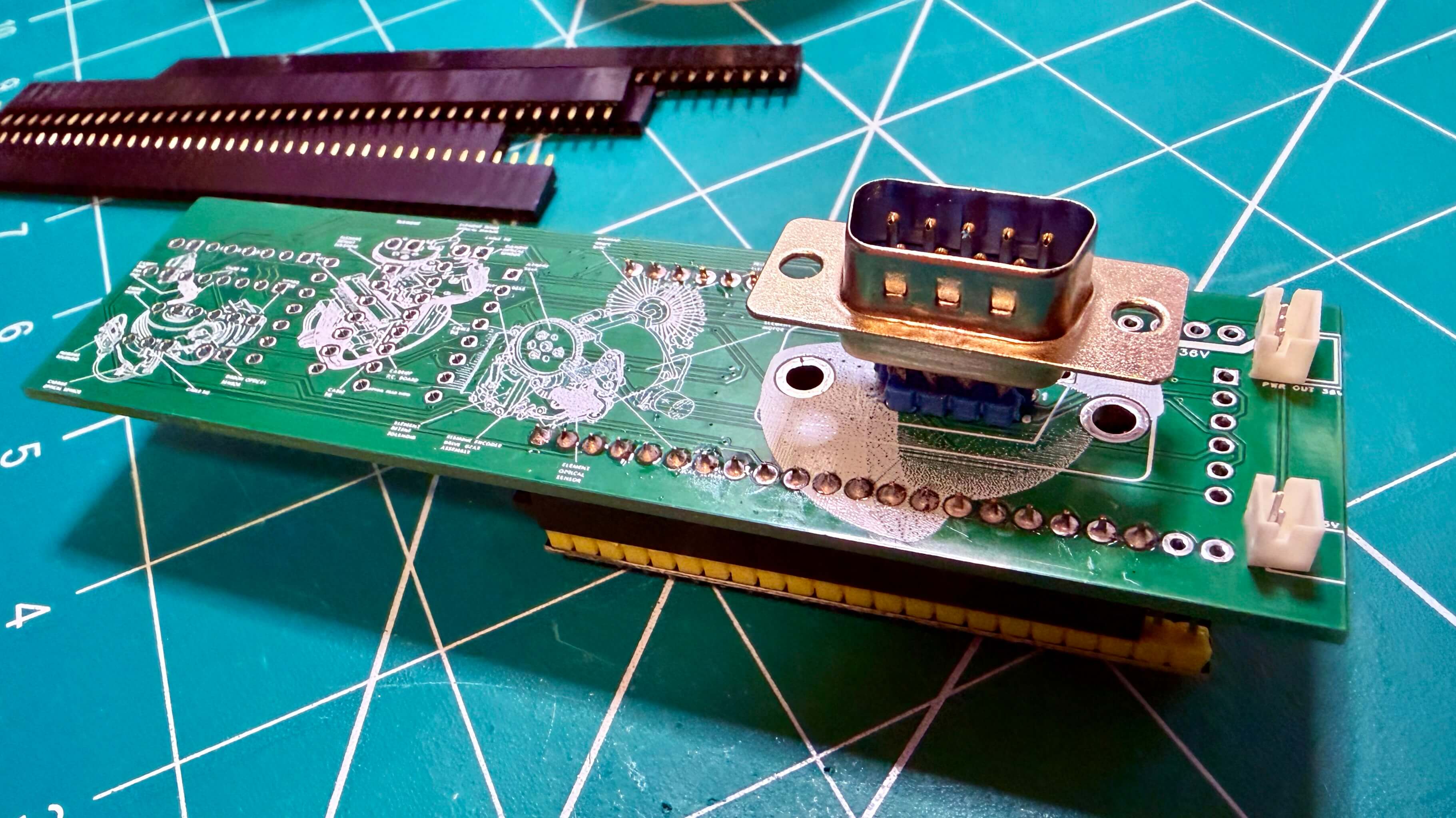
Beautiful.
I designed the PCB with 0402 resistors. 1 x 0.5mm. Smaller than a grain of rice. I was wayyyy overconfident.
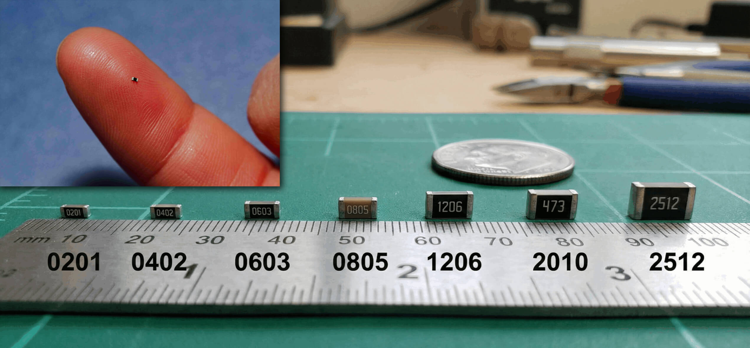
Plan was solder paste and hot air. Paste on the pads. Place components with tweezers. Heat until the paste reflows and surface tension pulls everything into alignment.
Surface tension does the work. That is the theory.
In practice:
Paste too much. Paste too little. Component slides off the pad. Component sticks to the tweezers. Tweezers flick, component gone forever. Hot air blows the component off before the paste reflows. Two pads bridge into a solder ball. Component lifts on one end and stands upright. That last one is called a tombstone. Looks like one too.
Rework. Flux. Tweezers. Hot air. Rework again.
Resistors packed between the DIP sockets with about 2mm of clearance. No room for error. Plenty of room for error anyway.
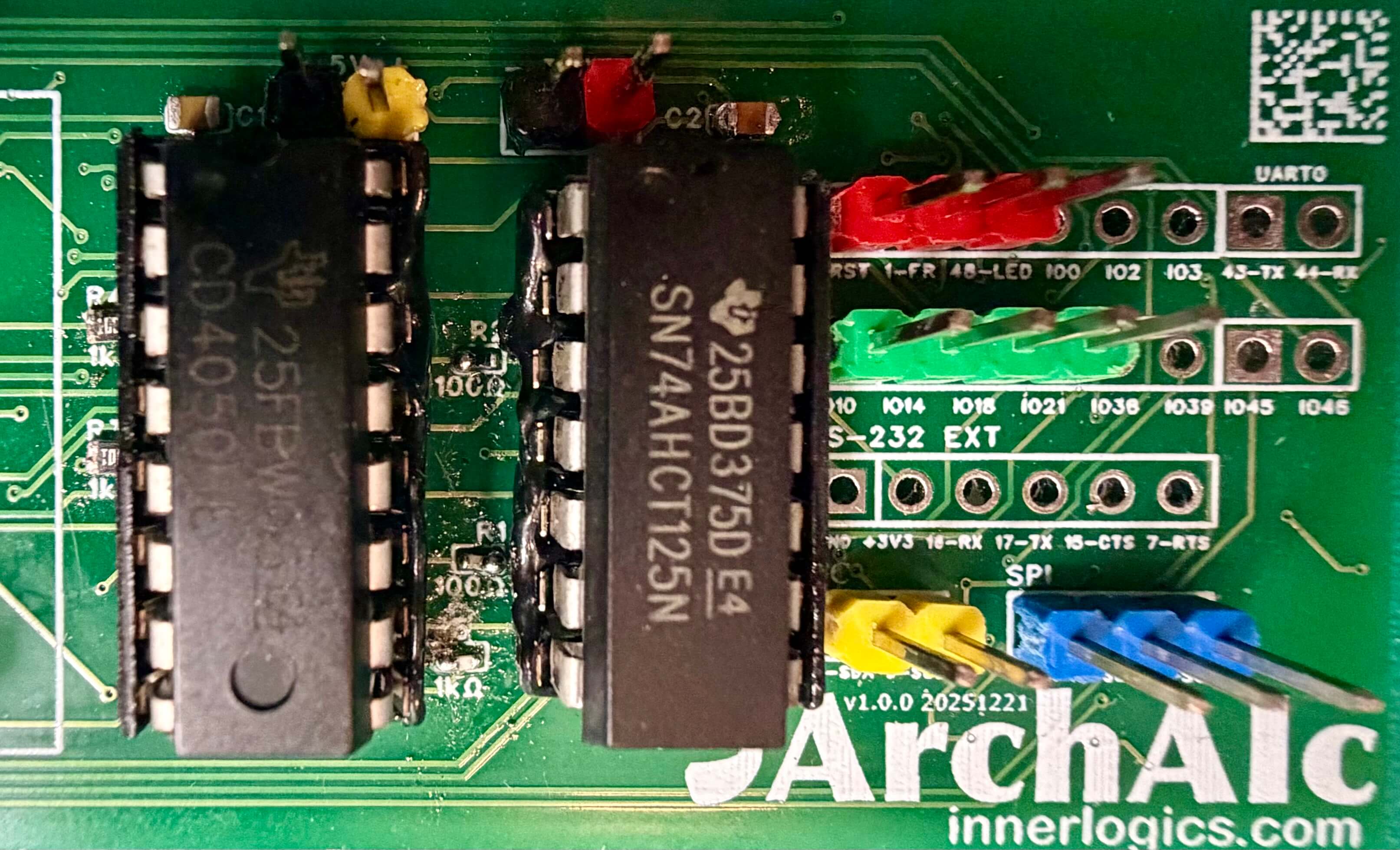
Eventually the board was populated. Flux residue wiped. Through-hole parts soldered, front and back. Continuity checked.
Good enough.
Asked Claude.ai what size I should use for the next PCB version.
I completely understand. 0402 components are genuinely challenging to hand solder.
- 0402: 1.0mm × 0.5mm (what you're struggling with)
- 0603: 1.6mm × 0.8mm (60% larger)
- 0805: 2.0mm × 1.25mm (150% larger than 0402)
My vote: Switch to 0603 and save your sanity.
Noted for v1.1. To save my sanity.
Plugged it in.
Nothing.
Same code. Same components. Prototype worked. PCB didn't.
TDATA stuck LOW. Typewriter protocol failing on startup.
Added debug logging. Every signal, every state transition.
Ran it on the prototype. Clean. TREQ goes LOW, TDATA goes HIGH, state machine transitions in order.
Ran it on the PCB.
TDATA=0 TREQ=1 STATE_REQUEST → collision
Chaos.
Checked the schematic. Twice. Traced every wire. Schematic was correct.
Stared at the board.
DE-9 male port on the back. I'd placed it on the bottom layer. The connector faces outward, so the dongle can attach to the typewriter.
I used a component I downloaded from EasyEDA. It's called DB9_M. M for Male, right? The 3D rendering shows it as a female, but I ignored it, because I was going to solder a male connector anyway.
Well, the connector pin numbering is directional. Mirror a resistor, nothing changes. Mirror a DE-9, every pin flips. Pin 1 becomes pin 9. Pin 4 becomes pin 6. Everything was going to the wrong pins.
Traces were perfect. Schematic was correct. Physical connector was 180 degrees from the typewriter interface.
Stupid mistake. Luckily, the 36V pin is at the center, mapped to the same pin number, no matter the orientation. This could have ended badly otherwise.
The fix will be crude.
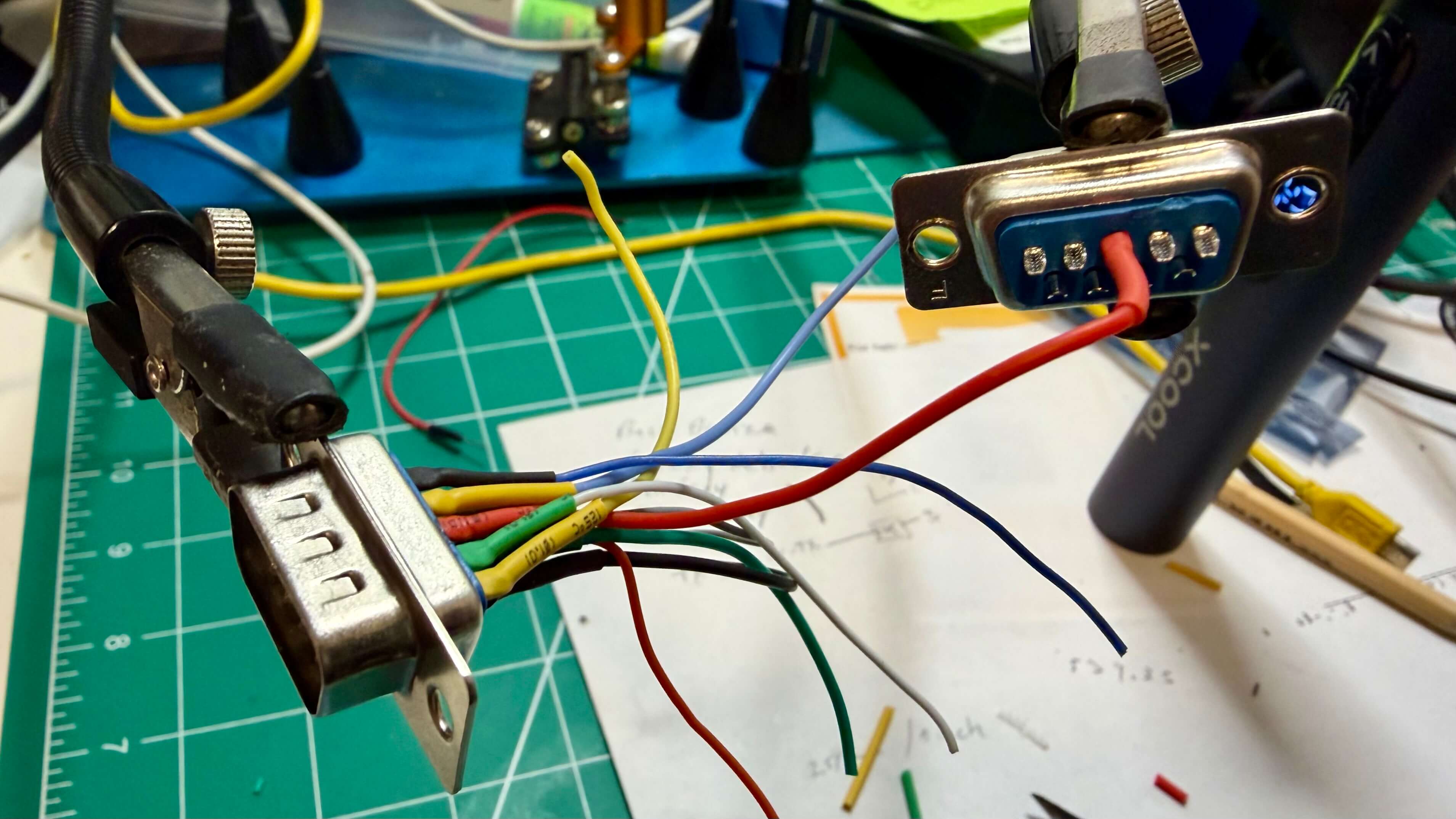
I am working on an adapter. DE-9 male on one end, female on the other, wired to cross the pins 180 degrees. Plug it between the PCB and the typewriter. A patch. Noted for v1.1.